Hi guys!
I am
posting all available material on the winding machine. This is the second version of the machine.
The first one worked for 10 years without any problems and now I wanted to
improve something. Namely, to replace the motors and a little rewrite the software.
The stepper motor remains on the stacker, but now it is not Chinese junk, but a
decent five-phase Japanese motor from Oriental Motor AR series. On the coil
drive is installed servo motor Panasonic Minas A5 200W and rated torque of
0.64N.m (maximum torque of 1.92N.m). All this stuff through a 4 to 1 gearbox, a
pair of gears with 100/25 teeth and a 15mm wide toothed belt (HDT 3M). With this modernization I got rid of
unnecessary noise, and the noise was pretty decent because of the rotation of
the coil by a stepper motor through a pair of metal gears with a reduction of
about 3 to 1.
A few
words on my understanding of winding organization. You need to be able to wind
one layer and count these layers. Everything else is highly secondary. As for
the mechanics itself, it should be convenient to install/remove spools, turn
them over and have maximum access to the spool. That is, the spool should be as
close to the operator as possible, the laying unit behind the spool, but not in
front of it. The headstock itself with controls can be either on the left or on
the right, as it is more convenient. I prefer the right side. Manual control of
the stacker and spool, for example, for initial positioning, only through an
encoder (MPG), as in CNC machine consoles. Other options, like buttons, are not
convenient, but we are not talking about industrial equipment, in which the
winding program is written and tested by a special person, and the operator
only charges the wire, insulation, etc. How to enter data ? It is clear that
the most convenient option is a numeric keypad, which is realized. Another very
important control organ is the coil speed regulator. It is realized by means of
potentiometer. It also has a function - full stop. For this purpose it is
enough to turn it to the minimum position.
I will
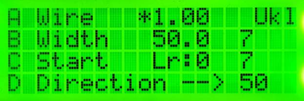
describe the logic of the software. Indication is realized through LCD 20x4.
The menu is one-level. Keyboard 4x4, realized long and short pressing of
buttons. Input of wire diameter up to the second decimal place (1,23mm, max.
9,99mm). Winding width input up to the first decimal place, maximum value
999.9mm. Stacker screw with a pitch of 5mm per revolution. Stacker stepper
motor 5000 pulses per revolution, which allows to realize simple, up to
0.001mm, calculations without error. The result is 1000 pulses per 1mm, which
gives 1/1000=0.001mm per step. For one revolution of the coil the stacker makes
10 shifts by 1/10 of the wire diameter. For example: a 1.23mm diameter wire
will be stacked in ten 1.23*1000/10=123 pulses movements. A 100p/r incremental encoder is mounted on
the coil shaft. Each pulse calls the external interrupt handler, which counts
turns and on each tenth pulse calls the step() function to send to the stacker
a pack of pulses in the amount of 1/10 of the total. At every hundredth pulse
the number of turns is added or subtracted.
The number of turns in a layer is calculated as the winding width
divided by the wire diameter and rounded down. There is an error here, which
can be taken into account at the end of each layer. The option is disabled by
default. The stacker carriage runs along the winding width, which is calculated
based on the number of turns. At the
same time the function of carriage return to the initial position and back is
realized. It is convenient if you wind layers from one cheek. If necessary, the
error compensation can be enabled from the keyboard, then the carriage will
return to the calculated winding width plus the error, i.e. to the entered
winding width value. As a result, it turns out that we enter only winding width
and winding pitch (wire diameter) from the keyboard. Since winding is still not
a precise thread cutting on a lathe and the first winding gives filling of the
layer in width not by one diameter, but by two, plus there are winding variants
with and without indentation, then by varying these two parameters you can
choose the desired one.
Short button press description:
"A" - when pressed, the previous
value of wire diameter (pitch) is reset to zero. Enter the new value from the numeric keypad
in the following way: to enter 1.23mm, press 123. For 0.23mm enter 023. For
0.05mm enter 005.
"B" - when pressed, the previous
winding width value is reset to zero.
Enter the new value from the numeric keypad as follows: to enter 123mm,
press 123. To enter 123.4mm, press 1234. For 12.3mm enter 0123. For 1.2mm enter
0012. For 0.2mm, enter 0002.
"C" - is the start/stop (pause) button
of the coil drive motor. Active only if the values of wire diameter and winding
width are entered. The calculated number of turns in the layer is greater than
zero.
"D" - changes the direction of
movement of the stacker carriage. The display is indicated by arrows.
"*" - selection of coil or stacker
for manual control via MPG encoder.
"#" - reset the number of wound turns
in the layer. After completing the layer winding, if the counter is not reset,
it will be prohibited to start the coil drive (button "C") When the
counter is reset, the variable "cont" is reset. This means that the reset
memorizes the position of the spool shaft, from which the counting of the
number of complete turns will start. Convenient if you need to wind on both
sides of the frame.
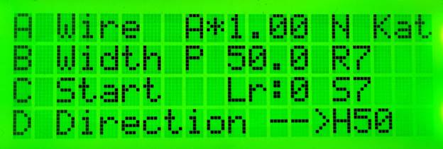
Description of the long button press:
"A" - activation of the Non Stop
mode. When the mode is activated, the letter "N" appears on the
display. In this mode, winding in automatic mode takes place. When the layer is
completed, the layer turns counter is reset and the carriage changes the
direction of movement. The machine stops only manually, e.g. when the total
coil count reaches the desired value or when the coil frame is filled with
wire.
"B" - activation of error
compensation at the end of each layer. When the mode is activated, the letter
"P" appears on the display.
"C" - deactivation of the
"Servo-On" signal of the coil drive. Display "S". Active at
zero value of wire diameter or winding width. The mode is necessary for manual
(by the shaft) rotation of the coil frame. The necessity of the mode is
debatable, but let it be.
"D" - returns the carriage to the
initial position after winding the layer. Since the distance calculation is
based on the winding width, the carriage will return to the beginning of
winding only after the layer winding is finished and the error is taken into
account. The error accounting is disabled by default.
"0" - High speed mode of the spool
shaft drive. Indication "H" on the display. In low speed mode, the
maximum spool speed is 7,5rp.sec, in high speed mode it is 15rp.sec (450 or 900 rpm).
"1" - Enable/disable slowdown at the
beginning and end of layer in Non Stop mode and only slowdown at the end of
layer for Auto mode. Indication "A" on the display when the mode is
deactivated. Variable "ACC" in the program code. It is specified as the number of turns at the beginning and end of the layer that will be wound at a reduced speed. The value of the variable also
depends on the entered wire diameter. In the main code of the program all this
can be changed to suit yourself. How
many times to reduce the speed can be set in the code of the generator, which
is made on the additional board Arduino Nano. There you can also set the speed
modes and modes of acceleration/deceleration of the coil shaft.
"*" - turns on the reverse mode.
Option for reverse wire winding (for bad layers). "R" indication. At
non-zero values of pitch and width, starts by pressing "C". It is
desirable to set the speed adjustment potentiometer to the minimum position
beforehand and winding is carried out with it.
A small example of layer winding:
Press
"A" and enter the wire diameter/step. Then press "B" and
enter the winding width. Press "*" to select the stacker or spool
control mode (Ukl / Kat). Use the MPG encoder to adjust the carriage to the
desired cheek, to the beginning of the winding. Switch manual control mode
"*" to spool control (indication "Kat") and set the spool
to the start position. Press "#" to reset the variable
"cont" and memorize the coil position for counting complete turns. Then there are two options. First, we can
manually rotate the MPG and watch how the first, initial turns of the layer are
laid, while adjusting the position of the stacker carriage. The second, we can start the coil drive motor
by pressing "C" and by adjusting the rotation speed with the
potentiometer we can lay the first turns.
You can even do this, twist the potentiometer to zero, press
"C" and by turning the potentiometer control the start of rotation
from the lowest speed. When the winding of the layer is completed (the number
of winded turns is equal to the calculated number of turns), in case the
winding was done by switching on the drive motor, it will be automatically
stopped and the direction of the stacker movement will be automatically
reversed. In case of a manual drive, the
numbers of windings must be monitored. Everything else is exactly the same as
with the motor. If you want to continue winding the next layer from the same
cheek, press long "D", the carriage will return to the initial
position. Further by means of MPG we either change the position of the bobbin
or not. The last action is to reset the number of windings in the layer
"#" with a short press. Or long press, all values, current windings
in the layer, total/all wound windings and number of layers will be reset.
A little
technical details of the implementation. So, as I wrote earlier, at 1000 pulses
per 1 millimeter of the stacker everything is considered very well, but there
is still a moment, and how it all has time? I will write at once that even at high speed (15 rev/sec) the stacker
has time to a diameter of 1.5 mm, which is with a large margin and already goes
beyond reason. And the stacker has time to work off a pack of pulses with the
value of 1/10 of the necessary for one step, in the interval of 3.6 degrees of
coil revolution. That is, in the time interval between two neighboring pulses
of the coil shaft encoder, which, let me remind you, is 100p/r. The whole
processing fits into just one interrupt call of the step() function.
The figures are as follows:
The
interval between two neighboring encoder pulses at 15 r/sec is 1/(15*100) =
667µs. The execution time of one clock cycle for the stacker is about 4.5µs. In
the code it is two 2µs delays plus some execution time, about 0.5µs. Let's do
the math for a wire diameter of 1mm. 1/10 pack equals 100 pulses. 100*4,5 =
450µs, which is within the 667µs interval with a margin. If the motor of the stacker does not allow
you to work so quickly with it, you can apply encoder 50p/r that will halve the
requirements, well, or make a disk encoder for 10 positions, which will
increase the time by 10 times. In reality, it is unlikely to need all this, as
thick wire is not necessary to wind quickly, and on a thin wire pulse pack
short. In the archive there is an excel file with a table for calculating
intervals.
For
example, just in auto mode, the slowing down of rotation occurs a few turns
before the end of the layer winding. The number of turns depends on the wire
diameter and the selected speed mode. In Non Stop mode the slowdown occurs both
at the beginning and at the end of the layer. The mode is enabled by default,
but it can be deactivated from the keypad.
ws-amp.eu